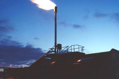
Every vent or safety valve outlet can be routed to a central point and be either vented to a safe loaction or burned. In case of an overpressure situation, or a purge prior to maintenance, all combustible gasses are disposed of safely. Operation is automatic, and maintenance is simple. Our systems are designed with state of the art software by our in-house EX specialists to ensure inherent safety.
Flaring reduces greenhouse gas emissions. We can help you reduce emissions further using an incinerator to burn the waste gas, condensate and other pollutants at extremely high temperatures.
- Reliable, proven technology helps assure high quality and safety
- Options include cold-vent, flare stack, or incinerator
Case studies
Dedication and hard work
Ras Al-Khair Power Plant (fuel gas system)
- What did our customer request?
-
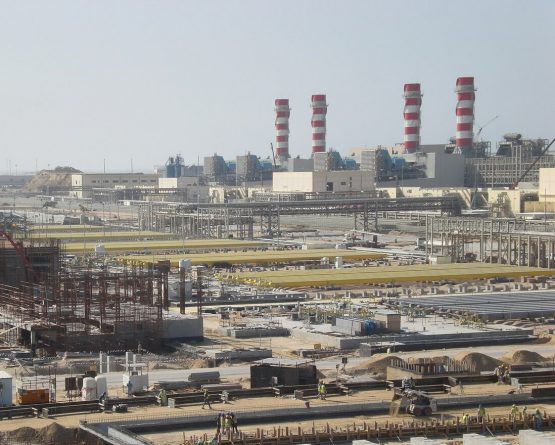
The Saline Water Conversion Corporation is a Saudi Government Corporation responsible for producing electric power and desalinating seawater. The SWCC Ras Al Khair project was at the time the largest combined power and desalination plant in the world and won the prestigious “Desalination plant of the year” award in 2015. It is a landmark project for SWCC.
The plant converts more than 1 billion litres of seawater into potable water each day, transforming the potable water situation in Riyadh, one of the world’s fastest growing and most water-stressed cities. The plant also produces 2400 MWe of electricity for the Eastern Province of Saudi Arabia and helps to power the nearby Ma’aden/Alcoa Aluminium plant.
The power plant is gas & oil fired, and Petrogas won the contract for the fuel gas conditioning station with 1 million Nm3/h capacity for 12 gas turbines, along with the backup fuel oil system to ensure a high quality, reliable and continuous supply of fuel for the turbines. Waste heat and reverse osmosis are used to desalinate 1 billion litres of sea water per day. - Our solution
-
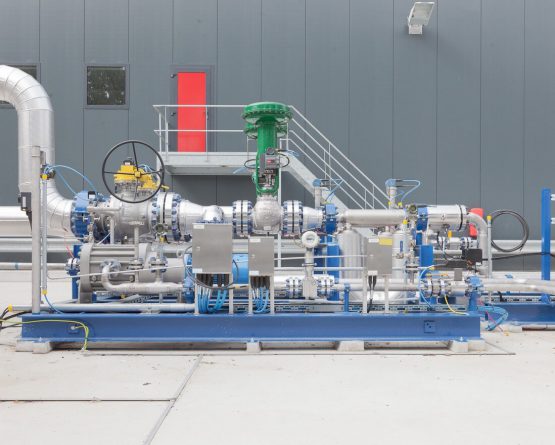
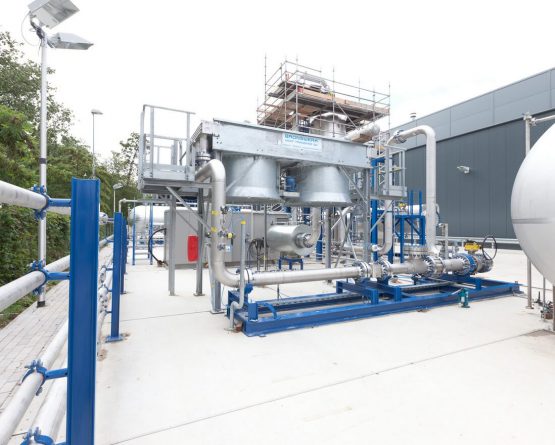
In close cooperation with the owners’ engineer Pöyry, we designed six identical blocks. Each had two mirrored gas conditioning systems including Emergency Shut-Down valves, filters, flow meters, heaters, pressure reducing systems for GTs and boilers, pressure boosting compressors and a high pressure gas buffer system. Petrogas built the skid-based system in workshops in the Netherlands and China, and erected and commissioned the system on site.
- What set the project apart?
-
Because Petrogas has both engineering and fabrication in-house, our customer benefitted from our practical experience in the initial basic design phase. The design was optimized before Petrogas built the skids, wrote the control software and performed the on-site commissioning.
The system can boost gas pressure for a prolonged period and can maintain gas supply for several minutes when the gas feed is interrupted to allow the turbines to switch to fuel oil. Petrogas played a substantial role in drawing up the operating philosophy between all these systems. - What were the project challenges?
-
“The sheer size of the project made it a challenge. The system is actually twelve complete 12” gas conditioning systems with 100% redundancy. The photo shows the stacks of the Water Bath Heaters, 36 in total.
Resources, planning, logistics between several workshops and dozens of suppliers all required a creative approach. The order came in 2011 when we already had a healthy backlog, and the order was worth about a year’s turnover. Petrogas successfully completed the job thanks to the dedication and hard work of our personnel and suppliers. “
- What did our customer request?
-
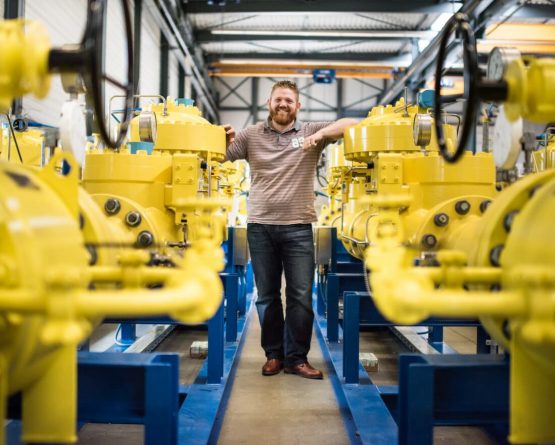
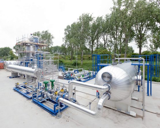
ProLabNL – based in Arnhem, the Netherlands – offers testing facilities that simulate oil field conditions with natural gas/raw oil and water (hydrocarbons) under high pressure, for instance to test liquid separators. Petrogas was approached by ProLabNL to create a high pressure test facility for subsea liquid separation.
- Our solution
-
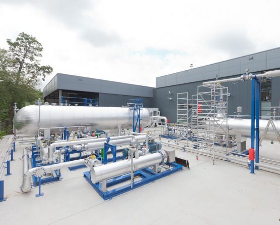
The installation was designed based on information provided by ExxonMobil for the testing of a subsea separator. ProlabNL used this information to create a process flow diagram, which Petrogas then elaborated into a piping and instrumentation diagram with the required materials list. Next, Petrogas provided for the 3D installation drawing, wiring diagrams and the purchase of components such as pumps, instrumentation, flow meters and valves.
- What set the project apart?
-
Withing Petrogas we established a close partnership with our customer in order to ensure the best performance of this test facility. Specially with respect to the material we used and the short notice changes we have performed successfully. The material which was used is suitable for the highly corrosive atmospheres and fluids. The opening of this project was performed by a member of the Royal Dutch family.
- What were the project challenges?
-
“The installation had to be designed in such a way that it would fit in the available space, that any emitted vapours could not be ignited by the nearby rail track, and that the could be depressurised within a certain amount of time. Petrogas furthermore supplied the information required for the nuisance act license and the fire department.”
Contact us
Would you like to discuss your project with our Experts? Please feel free to contact us.
Direct contact with our Experts
Your interest
Venting & Flaring
